logo
Buy Now
  • About
    • About us
    • Contact Us
    • Meet the Founder
    • Advisory Board
    • How It Works
      • System Overview
      • Web App Demo
  • Pricing
  • Blog
  • Success Stories
    • Testimonials
    • Case Studies
  • Resources
    • Installation & Setup Instructions
    • Web App Login
    • Installation Videos
    • Applications
  • Help
    • FAQ
    • Cut Sheets (Specifications)
    • Technical Drawings
    • Contact Us
  • Login
  • Address

    Dynamic Monitors
    16 Myrtle Street, Unit #1
    Stratford Business Park
    Stratford, PE
    Canada   C1B 2W2

logo
Buy Now
  • About
    • About us
    • Contact Us
    • Meet the Founder
    • Advisory Board
    • How It Works
      • System Overview
      • Web App Demo
  • Pricing
  • Blog
  • Success Stories
    • Testimonials
    • Case Studies
  • Resources
    • Installation & Setup Instructions
    • Web App Login
    • Installation Videos
    • Applications
  • Help
    • FAQ
    • Cut Sheets (Specifications)
    • Technical Drawings
    • Contact Us
  • Login
Onsite Insights Products SepticSitter Sewage SystemsFebruary 22, 2017

Drainage Stone That Doesn’t Drain?

By Kelly Galloway, P.Eng.
Trench fluctuations April 6/17 to May 24/17 showing significant discrepancies in levels

Drainage stone is supposed to drain. After all, typical 3/4″ to 1.5″ gravel used in septic trenches has a lot of void space. In my early days working at an engineering firm with a materials testing lab, I tested some typical, but fairly dirty, septic gravel and it had approximately 40% open space. So water should flow easily through that, right?

As part of our SepticSitterTM field validation program, we have been monitoring trench ponding levels in several leachfields located in PEI, Canada. We have observed some interesting results.

System Description

Mr. & Mrs. Buns (the name is made up but the system and data is real) have a 15 year old raised-bed, “Contour” drainfield. Contour drainfields were developed and popularized in Nova Scotia, Canada, and consist of a single (usually gravel) trench, with a level bottom, constructed to follow a natural contour of the land (across the slope). The trench for this three-bedroom home is 138 ft long by 4.5 feet wide. Mr. & Mrs. Buns are the only two occupants in the home now. It would have been loaded more heavily for several years after this system was first constructed when their children were also living at home.

Mr & Mrs Buns Contour trench under construction
Contour drainfield trench under construction in September 2000, just prior to final backfill.

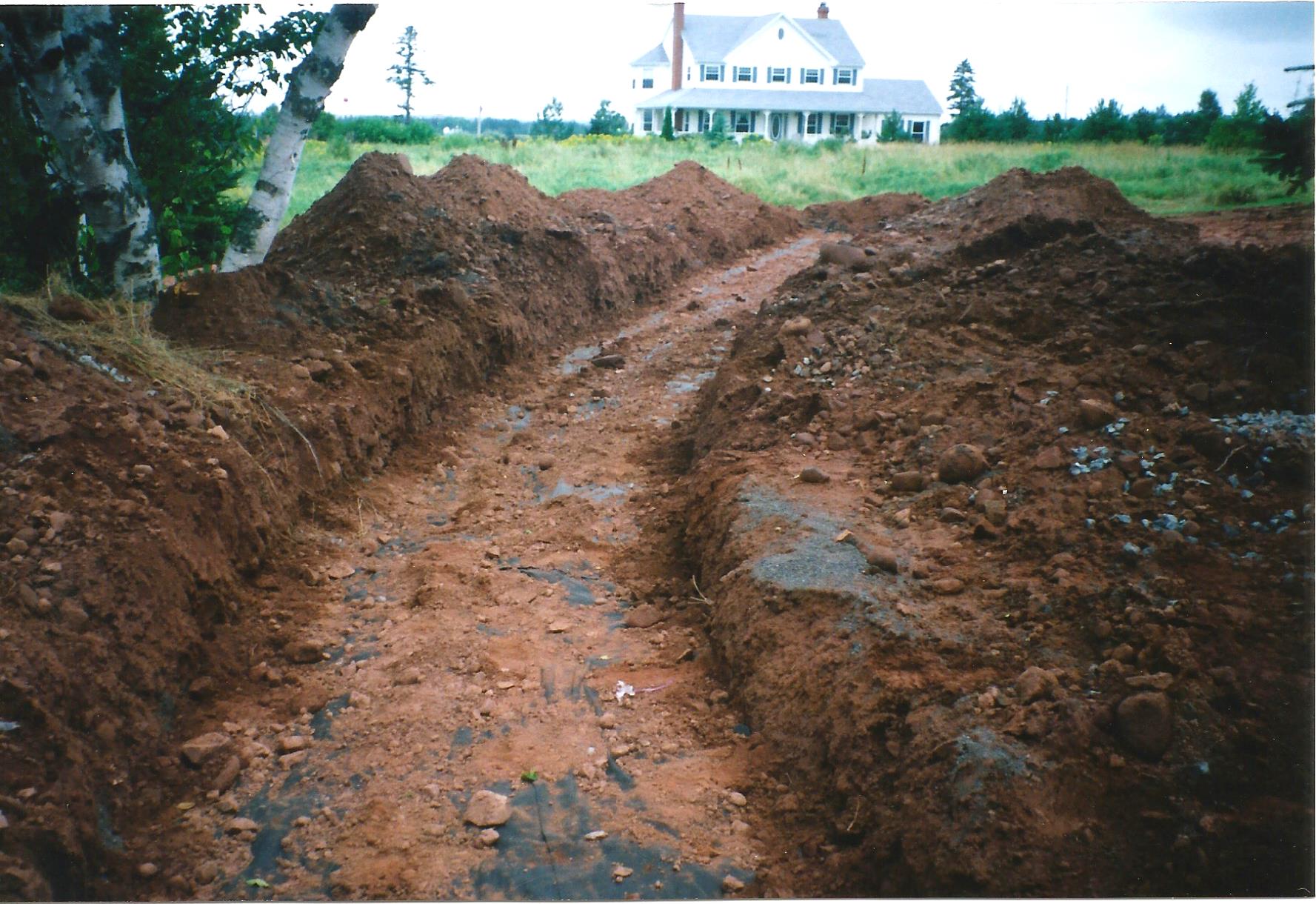
The trench is gravity trickle-fed at the midpoint with a Tee which attempts to cause the flow to split evenly in each direction. This often doesn’t happen in reality as most of the flow tends to go in one direction or the other.

Site plan of Mr. & Mrs. Buns septic system showing Septic Sitter sensor locations
Site plan of Mr. & Mrs. Buns septic system showing Septic Sitter sensor locations.

Liquid Levels Throughout Trench

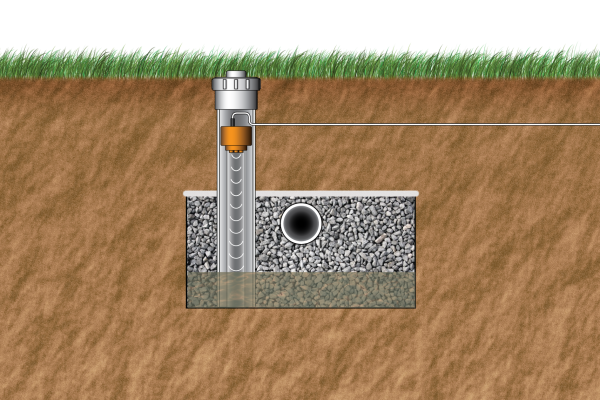
In 2015 we retrofitted inspection ports and installed SepticSitterTM sensors at three locations in the trench. The inspection ports extend down to the bottom of the gravel and permit monitoring of effluent ponding levels. We also installed a sensor in the septic tank.

Septic Sitter installed in gravel trench.
Three inspection ports containing SepticSitter ultrasonic sensors were retrofitted to the gravel trench to permit automatic monitoring of ponding levels.

As the data from the drainfield sensors show, the effluent distribution is not very even at all.

Trench fluctuations April 6/17 to May 24/17 showing significant discrepancies in levels

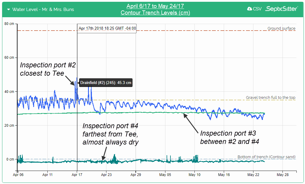
During times of high flow, rainfall events or snowmelt, the middle of the trench (inspection port #2) ponds to the top of the gravel or even higher (see the blue line on the graph). Otherwise, ponding levels fluctuate between 20cm to 35cm (8″ to 14″). At the location of sensor #3 (light green line on graph) the trench is typically ponded about 25cm (10″) deep with very little variation. But near the end of the trench, at location #4 (dark green line on graph), the trench is almost always empty.

What Is Going On..?

So why is this happening? The septic tank has had an effluent filter on it since the system was first installed, so I don’t believe that a lot of solids could have escaped from the tank and clogged the pipe or drainfield.

Dirty Stone Theory…

The stone used in this system was quite “dirty” and contained a lot of fines (sand, silt, clay). If you saw it however, I doubt you would think it was dirty enough to prevent water from flowing freely through it.

However, perhaps over the years, biofilm developed in between the gravel particles, so that it started to bridge the void spaces between the stones. Could biofilm have developed to the point where it has started to interfere with the free movement of effluent throughout the trench? That is my current theory, however I would be interested to hear what you think.

How would you investigate or remediate this system? In your experience, do you believe the gravel trench can be restored to a “free-draining” condition with more equal ponding levels throughout? Tell us your thoughts in the comments below!

dirty gravel, distribution, fines, ponding, retrofitting
Previous The “Internet of Things” goes underground with Septic Sitter!
Next Testimonial: Darcie Lanthier

Related Posts

The “Internet of Things” goes underground with Septic Sitter!

December 17, 2015

Detailed Septic Sitter data allows for unique “onsite insights”!

February 18, 2015

Design details for septic drainfield we are monitoring with Septic Sitter, Queens County, PE, Canada

February 19, 2015

Testimonial: Darcie Lanthier

November 6, 2017

7 Comments

  • Leah Boutilier
    March 14, 2017 at 1:20 pm
    I suspect variability in biomat formation throughout the trench may be the primary factor. If gravity-fed, the biomat will develop more in the area receiving the majority of the effluent holding effluent for longer periods. As you move away from the inlet T, less septic effluent will make its way there during regular use resulting in less biomat formation, and therefore less ponding during peak use or heavy rain. Variability in sand hydraulic conductivity may also be a factor.
    Reply
  • Dave dewar
    February 25, 2017 at 6:41 pm
    As one who has failed my first attempt at site Assesment ! Was the ditch perfectly level ? Personally I'm no fan of contour ! Any of them I see are to tthe point of leaking or the grass is heavy and wet that grows on top ! I don't know just something I have seen ! Very wet at one point in the ditch and dry at another point in the ditch ! Pipe has to be level for even distribution ! I'm a thinking ! Anyway have to catch up to you ! Thanks be in touch !!
    Reply
  • George
    February 23, 2017 at 12:57 pm
    We have done quite a bit of research on this issue and have verified what you have seen but not so dramatic a difference. I believe that the stone bridges/dams in areas so that the ponding levels across the bottom can be different. As the one area gets loaded (since in gravity fed systems there is ALWAYS differential loading in the trenches, areas of the bottom and sidewall thin and thicken causing occasional "breaks" in the dam and then you get some evening of the levels. We have only observed this with pipe-stone systems. I do not believe that it has any relationship with the fines in the stone, since in out experiments we had REALLY clean stone (<0.1% fine material).
    Reply
  • Garry-Lee Espinosa
    February 23, 2017 at 12:45 pm
    I think you are correct with the biofilm theory. However, I'm not sure it's biofilm plugging the void spaces between 1/2 - 3/4" gravel particles. I think the biofilm growth is in the soil below the gravel. "Dirty Stone" would also exacerbate the failure of the soil with fines. We see this same thing with septic tanks that gravity feed to a d-box. The beginnings of the trench will be the first to experience ponding because it gets the highest loading rate as effluent is absorbed long before it gets to the end of the trench. As the beginning trench develops a biofilm, inhibiting absorption of the effluent, the effluent is pushed down the trench to other parts that don't have the biofilm growth on it. I've always been told that this is called a "progressive failure" and common for gravity fed drainfields. One reason Orenco has always advocated pressure distribution as the only means of ensuring equal distribution along a drainfield trench.
    Reply
  • Bernie MIller
    February 23, 2017 at 11:04 am
    I agree with the theory and have witnessed it myself on a few occasions. We have even seen this happen in a bed with pressure distribution. In most remedation cases we use a terralift and some pretreatment or a combination of both.
    Reply
  • Stw
    February 23, 2017 at 9:48 am
    Are your retrofitted ports connected via a t to the perforated pipe, or are they sunk into the gravel trench
    Reply
  • John Roy
    February 23, 2017 at 9:46 am
    I have seen in the past that if they used Lime Stone that the powder that washed off the stone will clog the underside of the stone area. Then the water can not get to the sand base.
    Reply

Leave a comment or Cancel Reply

  • Product

    • Residential
    • Features
    • How It Works
    • Testimonials
  • About

    • About us
    • Advisory Board
    • Media
    • Jobs
    • Contact Us
  • Help

    • FAQ
    • Setup Guide
    • Installation Videos
    • Knowledge Base
    • Installation & Setup Instructions
    • Facebook
    • Twitter
    • YouTube
U.S. Patent No. 8100006, Canadian No. 2598215 | © 2019 Dynamic Monitors | Privacy Policy